Zephyr on Adafruit ESP32-S3 Feather - How to set Stemma I2C Power GPIO

Hi,
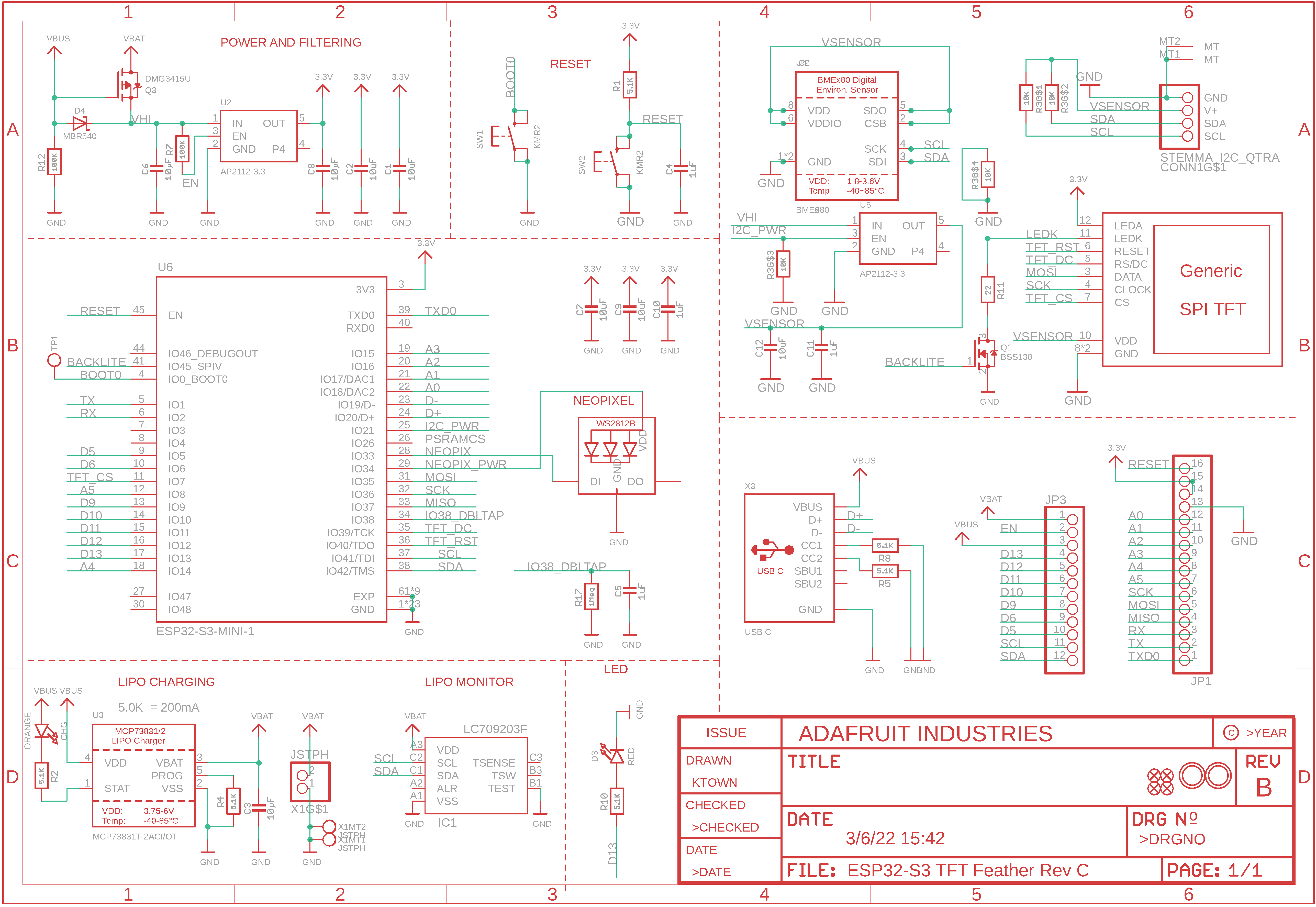
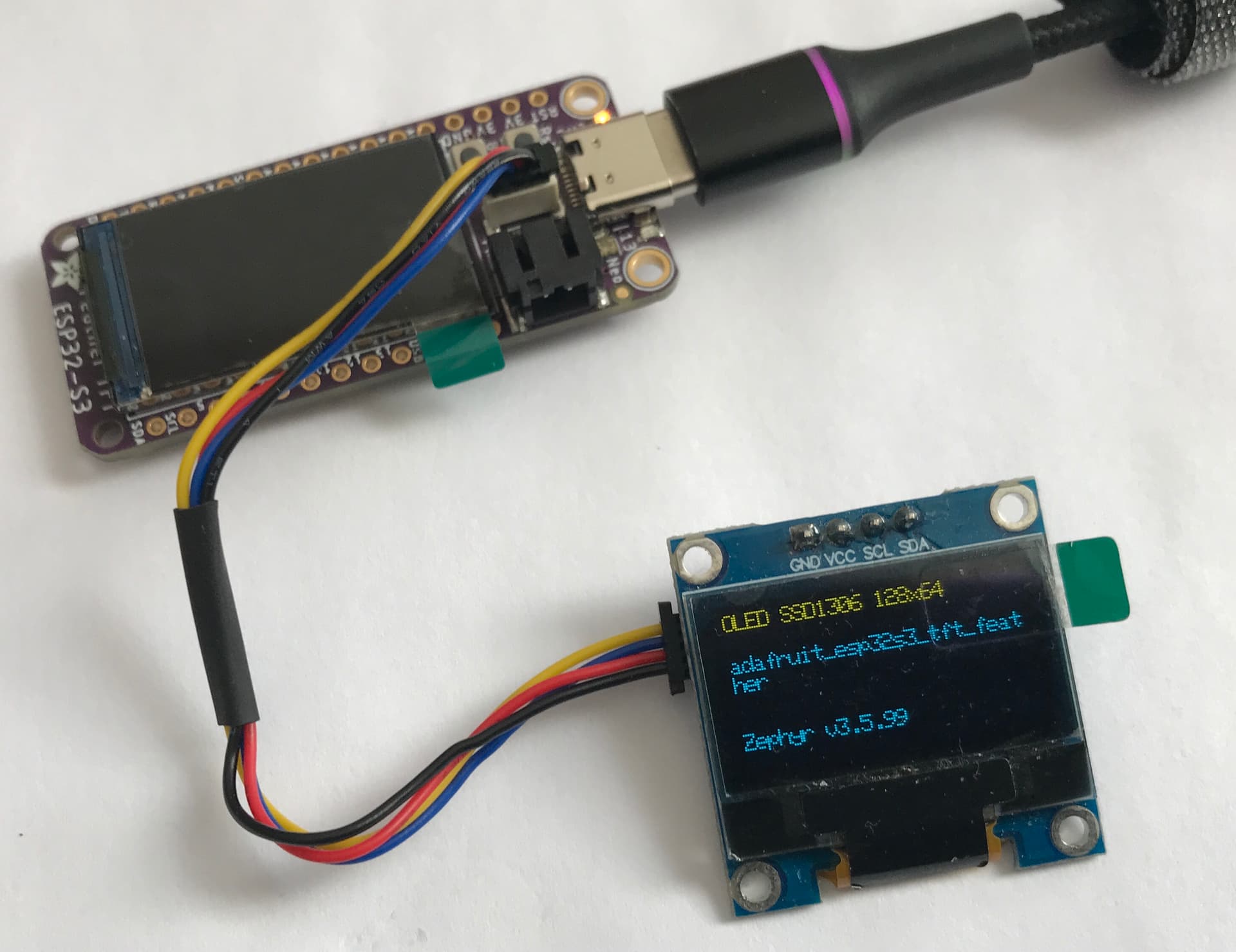
I’m currently running Zephyr 3.5.0 on Adafruit ESP32-S3 Feather boards (Feather and TFT Feather) using board xiao_esp32s3.

The ESP32-S3 Feather boards use the ESP32-S3 Mini-1 SoC. Everything seems to be fine, although the xiao_esp32s3 devicetree doesn’t have the Feather Connector definition, I can access the GPIOs directly.

I have submitted a request to Zephyr for adding these boards to the repo.

The ESP32-S3 Feather boards have a I2C STEMMA connector, power to which is controlled be setting a I2C_POWER GPIO high so that the I2C STEMMA gets used instead of the I2C pins on the Feather boards.

On the Adafruit ESP32-S3 TFT board with OLED SSD1306 connected via the I2C STEMMA, I’m setting the I2C_POWER GPIO pin correctly but I’m not able to get the OLED display to power.

Does anyone have experience running Zephyr on these Adafruit ESP32-S3 Feather boards?

In Arduino, the STEMMA I2C_POWER GPIO is done in “Setup” by configuring the GPIO as an output pin and setting it High.
`

  pinMode(TFT_I2C_POWER, OUTPUT);
  digitalWrite(TFT_I2C_POWER, HIGH);


Any help would be greatly appreciated. Thank you.

I’m setting the I2C_POWER GPIO in Zephyr as below.
Is this correct or do I need to set the GPIO before the I2C drivers are initialized? If so, How?

snippet from esp32-s3 overlay:


 / {
	chosen {
		zephyr,display = &ssd1306;
	};
````Preformatted text`

	leds {
		compatible = "gpio-leds";

		led0: led_0 {
				gpios = <&gpio0 13 GPIO_ACTIVE_LOW>;
				label = "BUILTIN LED";
			};

		ext_led1: led1 {
			gpios = <&gpio0 17 GPIO_ACTIVE_HIGH>;
			label = "LED 1"; 
		};
		ext_led2: led2 {
			gpios = <&gpio0 9 GPIO_ACTIVE_HIGH>;
			label = "LED 2";
		};

		tftpower_i2c: tftpower_i2c_0 {
			gpios = <&gpio0 21 (GPIO_ACTIVE_HIGH)>;
		};
	};

	aliases {
		led1 = &ext_led1;
		led2 = &ext_led2;
		tftpower = &tftpower_i2c; //TFT_I2C_POWER
	};
};


snippet from I2C_POWER init:

	// set TFT I2C POWER high
	if (!gpio_is_ready_dt(&tftpower)) {
		LOG_INF("Error: tftpower %s is not ready; ignoring it\n",tftpower.port->name);
	}

	if (gpio_pin_configure_dt(&tftpower, GPIO_OUTPUT) < 0) {
		LOG_INF("Error: failed to configure tftpower device %s pin %d\n",tftpower.port->name, tftpower.pin);
	} else 
		LOG_INF("Set up TFT POWER at %s pin %d\n", tftpower.port->name, tftpower.pin);
    
	gpio_pin_set_dt(&tftpower, 1);

@mike
Hi Mike,

Any thoughts on the above post, as to how I should be setting the GPIO that controls the power to the Stemma I2C connector?

The I2C_PWR GPIO21 isn’t exposed on the Feather board pins.

Should I be defining the tftpower_i2c pin under compatible = "gpio-leds" or this isn’t the correct method?

The west espressif monitor output shows that SSD1306 OLED isn’t being initialized.

btw - The OLED SSD1306 works fine if I connect it to the SDA/SCK pins on the board. The SDA/SCK pins are the same as those on the I2C STEMMA connector.

quark11:ssd1306_cfb_custom_fonts_tft_feather quark11$ west espressif monitor
Serial port /dev/cu.usbmodem14201
Connecting...
Detecting chip type... ESP32-S3
--- idf_monitor on /dev/cu.usbmodem14201 115200 ---
--- Quit: Ctrl+] | Menu: Ctrl+T | Help: Ctrl+T followed by Ctrl+H ---
ESP-ROM:esp32s3-20210327
Build:Mar 27 2021
rst:0x15 (USB_UART_CHIP_RESET),boot:0x8 (SPI_FAST_FLASH_BOOT)
Saved PC:0x400490cf
SPIWP:0xee
mode:DIO, clock div:2
load:0x3fcd0108,len:0x164c
load:0x403b6000,len:0xc68
load:0x403ba000,len:0x30e8
SHA-256 comparison failed:
Calculated: 602f92c26a1cbfae41988d8e2fd1ed307ce91434aabbe15f7945181ae4f0307a
Expected: ffffffffffffffffffffffffffffffffffffffffffffffffffffffffffffffff
Attempting to boot anyway...
entry 0x403b61f4
I (45) boot: ESP-IDF 67fa60bdff 2nd stage bootloader
I (46) boot: compile time 00:42:22
I (46) boot: chip revision: 0
I (48) boot.esp32s3: Boot SPI Speed : 40MHz
I (52) boot.esp32s3: SPI Mode       : DIO
I (57) boot.esp32s3: SPI Flash Size : 4MB
I (62) boot: Enabling RNG early entropy source...
I (67) boot: Partition Table:
I (71) boot: ## Label            Usage          Type ST Offset   Length
I (78) boot:  0 nvs              WiFi data        01 02 00009000 00006000
I (86) boot:  1 phy_init         RF data          01 01 0000f000 00001000
I (93) boot:  2 factory          factory app      00 00 00010000 00100000
I (101) boot: End of partition table
I (105) esp_image: segment 0: paddr=00010020 vaddr=00000020 size=0001ch (    28) 
I (113) esp_image: segment 1: paddr=00010044 vaddr=3fc90ee0 size=008d8h (  2264) load
I (122) esp_image: segment 2: paddr=00010924 vaddr=3fc917b8 size=00268h (   616) load
I (130) esp_image: segment 3: paddr=00010b94 vaddr=40374000 size=05400h ( 21504) load
I (145) esp_image: segment 4: paddr=00015f9c vaddr=00000000 size=0a09ch ( 41116) 
I (157) esp_image: segment 5: paddr=00020040 vaddr=3c000040 size=0352ch ( 13612) map
I (161) esp_image: segment 6: paddr=00023574 vaddr=00000000 size=0ca84h ( 51844) 
I (176) esp_image: segment 7: paddr=00030000 vaddr=42030000 size=0ae68h ( 44648) map
I (190) boot: Loaded app from partition at offset 0x10000
I (190) boot: Disabling RNG early entropy source...

[00:00:00.728,000] <err> i2c_esp32: I2C transfer error: -116
[00:00:00.728,000] <err> ssd1306: Failed to initialize device!
*** Booting Zephyr OS build zephyr-v3.5.0-4872-gcf14d4f1fd6d ***
[00:00:00.728,000] <inf> main: main_thread
Display device not ready
[00:00:00.728,000] <dbg> cfb: cfb_framebuffer_init: number of fonts 2
[00:00:01.228,000] <err> i2c_esp32: I2C transfer error: -116
[00:00:01.228,000] <err> ssd1306: Failed to write command
[00:00:01.728,000] <err> i2c_esp32: I2C transfer error: -116
[00:00:01.728,000] <inf> display: Index[0] font dimensions  5x8
[00:00:01.728,000] <inf> display: Index[1] font dimensions  8x8
[00:00:01.728,000] <inf> display: Selected font: index[3]
[00:00:01.728,000] <inf> display: x_res 128, y_res 64, ppt 8, rows 8, cols 128
[00:00:01.728,000] <inf> display: Zephyr v3.5.99

[00:00:01.728,000] <inf> display: xiao_esp32s3
[00:00:02.229,000] <err> i2c_esp32: I2C transfer error: -116
[00:00:02.229,000] <err> ssd1306: Failed to write command
Could not finalize framebuffer (err -1)
[00:00:03.229,000] <err> i2c_esp32: I2C transfer error: -116
[00:00:03.229,000] <err> ssd1306: Failed to write command
Could not finalize framebuffer (err -1)
[00:00:04.229,000] <err> i2c_esp32: I2C transfer error: -116
[00:00:04.229,000] <err> ssd1306: Failed to write command
Could not finalize framebuffer (err -1)
uart:~$

Thanks.

I’ve made some progress in getting ESP32-S3 TFT Feather working with OLED SSD1306 using the I2C STEMMA connector.

I came across @cdwilson 's blog on how to enable power regulator automatically when Zephyr boots up. The feature doesn’t require any code change.

The Adafruit ESP32-S3 Feather boards use a GPIO to control power to the I2C on the Stemma connector. So, I tried using Zephyr’s regulator binding.


	reg_tft_power: reg-tft-power {
		compatible = "regulator-fixed";
		regulator-name = "reg-adafruit";
		enable-gpios = <&gpio0 21 GPIO_ACTIVE_HIGH>;
		regulator-boot-on;
	};

I’m able to enable/disable regulator power to I2C STEMMA connector.

However, it only seems to work if I have another OLED SSD1306 hooked up to the ESP32-S3 I2C pins. Weird!

Anyway some progress in the right direction.

Chris @cdwilson, would you know how I fix the above weird issue? Thanks.

btw - Golioth have been awesome with so many articles and training material on Zephyr. It’s much appreciated!

Based on this, it sounds like there is a current hardware configuration that is working correctly? (sorry, I’m trying to piece together from the above posts, and I’m not exactly clear on what the “weird issue” is)

If so, then it sounds like you’ve got the SW config working but there may be a hardware issue. Things I would try:

  • Does the “other” OLED SSD1306 have onboard I2C pull-up resistors? If so, it’s possible that the firmware is trying to drive the bus too fast and without the other OLED, there is not enough pull-up strength to support the speed you’re trying to run the I2C bus at. What is the bus speed you’re using? Try setting a slower I2C bus speed like 100 kHz and see if that fixes the issue (alternatively you could try adding parallel pull-up resistors to increase the pull-up drive strength).
  • Can you probe the I2C signals with a scope on the OLED side? Do you see any activity on the I2C bus? Does the signal look clean?

@cdwilson - Thanks for the quick response.

I’m running I2C at I2C_BITRATE_STANDARD (100 kHz).

I expected this to work, as the ESP32-S3 TFT Feather connected to the OLED SSD1306 works fine under Arduino. They set the TFT_I2C_POWER GPIO high before the I2C / SSD1306 drivers load. No hardware modification is required.

// Initialize variant/board, called before setup()
void initVariant(void)
{
  // This board has power control pins, and we must set them to output and high
  // in order to enable the NeoPixels, TFT & I2C
  pinMode(NEOPIXEL_POWER, OUTPUT);
  digitalWrite(NEOPIXEL_POWER, HIGH);
  pinMode(TFT_I2C_POWER, OUTPUT);
  digitalWrite(TFT_I2C_POWER, HIGH);
}

Unfortunately I don’t have a scope to probe the I2C.

However, when I have only ESP32-S3 TFT Feather connected to the OLED display, in the Espressif monitor output I see that I2C is ready but SSD1306 is disabled and has failed to initialize.

[

00:00:00.228,000] <err> i2c_esp32: I2C transfer error: -14
[00:00:00.228,000] <err> ssd1306: Failed to initialize device!
*** Booting Zephyr OS build zephyr-v3.5.0-4872-gcf14d4f1fd6d ***
[00:00:00.228,000] <inf> main: main_thread
Display device not ready
[00:00:00.228,000] <dbg> cfb: cfb_framebuffer_init: number of fonts 2
[00:00:00.317,000] <inf> display: Index[0] font dimensions  5x8
[00:00:00.317,000] <inf> display: Index[1] font dimensions  8x8
[00:00:00.317,000] <inf> display: Selected font: index[3]
[00:00:00.317,000] <inf> display: x_res 128, y_res 64, ppt 8, rows 8, cols 128
[00:00:00.317,000] <inf> display: Zephyr v3.5.99

[00:00:00.317,000] <inf> display: xiao_esp32s3
uart:~$ device list
devices:
- rtc@60021000 (READY)
- gpio@60004800 (READY)
- gpio@60004000 (READY)
- trng@6003507c (READY)
- uart@60000000 (READY)
- uart@60038000 (READY)
- i2c@60013000 (READY)
- reg-tft-power (READY)
- ssd1306@3c (DISABLED)
uart:~$

I understand your point regarding the firmware trying to drive the bus too fast. It may be the case. However, under Arduino the OLED connected to the I2C STEMMA works fine.

If I don’t use the regulator devicetree binding, How and What’s the best way to set TFT_I2C_POWER HIGH before the I2C/SSD1306 drivers load?

Do I need to perform a GPIO initialization in a PRE_KERNEL system init? If so, can you point to an example?

Thanks.

You can use gpio-hog in the devicetree overlay file to set a pin high or low during initialization. You’ll need to hunt in the Zephyr docs/sample code for how to do this. Last time I looked it was not well documented.

Hi Mike,

I’ll follow-up. Thank you.

Here are some further tests using the regulator binding method to set I2C Power on the Adafruit ESP32-S3 TFT Feather board.

There is 3.26V at the I2C STEMMA connector, SDA and SCK pins also have valid signal levels. This means that the firmware is sending I2C data correctly continuously to the display, as expected.

Given that the first 2 errors are I2C transfer error and ssd1306: Failed to initialize device! occur before the “*** Booting Zephyr …”, it appears that the initialisation sequence is an issue.

How do I check and modify the order of I2C, SSD1306, Regulator priorities in Zephyr? I think once this is done, the display will work.

================================================================

Setup:
`OLED SSD1306 is connected to the ESP32-S3 TFT Feather via the I2C STEMMA connector.

Regulator binding in adafruit_esp32s3_tft_feather.overlay:

reg_tft_power: reg-tft-power {
	compatible = "regulator-fixed";
	regulator-name = "reg-adafruit";
	enable-gpios = <&gpio0 21 GPIO_ACTIVE_HIGH>;
	regulator-boot-on;
};

Code snippet for output below:

void oled_display(void)
{
char os_ver[32];
int err;

uint32_t ver = sys_kernel_version_get();
snprintf(os_ver,sizeof(os_ver),"Zephyr v%d.%d.%d",SYS_KERNEL_VER_MAJOR(ver), \
	SYS_KERNEL_VER_MINOR(ver),SYS_KERNEL_VER_PATCHLEVEL(ver));
	
LOG_INF("%s\n",os_ver);
LOG_INF(CONFIG_BOARD);
while (1) {
    cfb_print(dev,CONFIG_BOARD, 0, 2*ppt);
    cfb_print(dev, "", 0, 1*ppt);
    cfb_print(dev, "OLED SSD1306 128x64", 0, 0);
    cfb_print(dev, "", 0, 3*ppt);
    cfb_print(dev, "", 0, 4*ppt);
    cfb_print(dev, "", 0, 5*ppt);
    cfb_print(dev, os_ver, 0, 6*ppt);
    
    err = cfb_framebuffer_finalize(dev);
	if (err) {
		printk("Could not finalize framebuffer (err %d)\n", err);
	}
    k_sleep(K_MSEC(500));
}

}

espressif monitor output:

[00:00:00.228,000] i2c_esp32: I2C transfer error: -14
[00:00:00.228,000] ssd1306: Failed to initialize device!
*** Booting Zephyr OS build zephyr-v3.5.0-4872-gcf14d4f1fd6d ***
[00:00:00.228,000] main: main_thread
Display device not ready
[00:00:00.228,000] cfb: cfb_framebuffer_init: number of fonts 2
[00:00:00.317,000] display: Index[0] font dimensions 5x8
[00:00:00.317,000] display: Index[1] font dimensions 8x8
[00:00:00.317,000] display: Selected font: index[3]
[00:00:00.317,000] display: x_res 128, y_res 64, ppt 8, rows 8, cols 128
[00:00:00.317,000] display: Zephyr v3.5.99

[00:00:00.317,000] display: adafruit_esp32s3_tft_feather
uart:~$ device list
devices:

  • rtc@60021000 (READY)
  • gpio@60004800 (READY)
  • gpio@60004000 (READY)
  • trng@6003507c (READY)
  • uart@60000000 (READY)
  • uart@60038000 (READY)
  • i2c@60013000 (READY)
  • reg-tft-power (READY)
  • ssd1306@3c (DISABLED)
    uart:~$

Output on regulator disable. Re-enabling the regulator stops the the I2C transfer errors.

uart:~$ regulator disable reg-tft-power
[00:26:06.518,000] i2c_esp32: I2C transfer error: -116
[00:26:06.518,000] ssd1306: Failed to write command
Could not finalize framebuffer (err -1)
[00:26:07.519,000] i2c_esp32: I2C transfer error: -116
[00:26:07.519,000] ssd1306: Failed to write command
Could not finalize framebuffer (err -1)
[00:26:08.519,000] i2c_esp32: I2C transfer error: -116
[00:26:08.519,000] ssd1306: Failed to write command
Could not finalize framebuffer (err -1)
uart:~$

Hi Mike.

I tried using gpio-hog as below.

`&gpio0 {
	status = "okay";

	i2c-tft-power {
		gpio-hog;
		gpios = <21 GPIO_ACTIVE_HIGH>;
		output-high;

	};
};

I’m able to confirm that the power to the OLED SSD1306 on the I2C STEMMA connector comes on, as it did with regulator devicetree binding but the display still doesn’t show anything.

From the “west espressif monitor”, I’ve confirmed that I2C is in a READY state but the SSD1306 failed to initialize. I do see 3.26V at the display connected via the I2C STEMMA and the SDA/SCK signals look fine. I2C is happily send commands/data to the display. There are no crashes on the ESP32-S3 and shell works fine.

I suspect that in both cases (regulator with GPIO control and gpio-hog), there is a sequence issue.

I may try to check if GPIO is HIGH in the code and then see if I can re-init the SSD1306 driver.

Is there a way to re-init a Zephyr driver from within the user’s program? If not, then I may try using a SYS_INIT() with PRE_KERNEL.

Thanks!

@mike , @cdwilson ,

Thank you for your assistance.

I got the SSD1306 to work with the ESP32-S3 TFT Feather I2C STEMMA connector using the gpio-hog had to extend the delay in the SSD1306 init.

The SSD1306 driver allows to set a delay in init using ready-time-ms DT property. The default is 10 milliseconds. I ended up extending it to 250ms.

Verified that the driver init sequence is correct, gpio-hog -> i2c -> ssd1306

EARLY
PRE_KERNEL_1
__init___device_dts_ord_32: clock_control_esp32_init(__device_dts_ord_32)
__init_init_mem_slab_obj_core_list: init_mem_slab_obj_core_list(NULL)
__init_statics_init_pre: statics_init(NULL)
__init___device_dts_ord_7: gpio_esp32_init(__device_dts_ord_7)
__init___device_dts_ord_68: gpio_esp32_init(__device_dts_ord_68)
__init___device_dts_ord_53: entropy_esp32_init(__device_dts_ord_53)
__init___device_dts_ord_54: uart_esp32_init(__device_dts_ord_54)
__init___device_dts_ord_57: serial_esp32_usb_init(__device_dts_ord_57)
__init_uart_console_init: uart_console_init(NULL)
PRE_KERNEL_2
__init_sys_clock_driver_init: sys_clock_driver_init(NULL)
POST_KERNEL
__init_enable_logger: enable_logger(NULL)
__init_enable_shell_uart: enable_shell_uart(NULL)
__init_malloc_prepare: malloc_prepare(NULL)
__init_k_sys_work_q_init: k_sys_work_q_init(NULL)
__init_gpio_hogs_init: gpio_hogs_init(NULL)
__init___device_dts_ord_70: i2c_esp32_init(__device_dts_ord_70)
__init___device_dts_ord_72: ssd1306_init(__device_dts_ord_72)
__init___device_dts_ord_8: dht_init(__device_dts_ord_8)
APPLICATION
__init_lvgl_init: lvgl_init(NULL)
SMP

Next challenge - Figure out why the onboard ST7789 TFT display isn’t coming up. Most likely some ST7789 init issue again.